3D digitization for reverse engineering.
With reverse engineering, like its name says, the usual and natural process is invested to reach the manufacture of a product.
“Reverse engineering” is a process by which engineers carefully disassemble an object or device to understand its internal workings without access to the original instruction manual. This approach is valuable for various applications, such as product improvement, understanding competitors, and identifying potential vulnerabilities in security devices. However, it is essential to remember that reverse engineering must be conducted in an ethical and legal manner.
In the reverse engineering process, special tools like 3D scanners are used to accurately capture the shape and structure of a physical object in the form of a three-dimensional point cloud. This point cloud represents the external surface of the object and contains detailed information about its geometry.
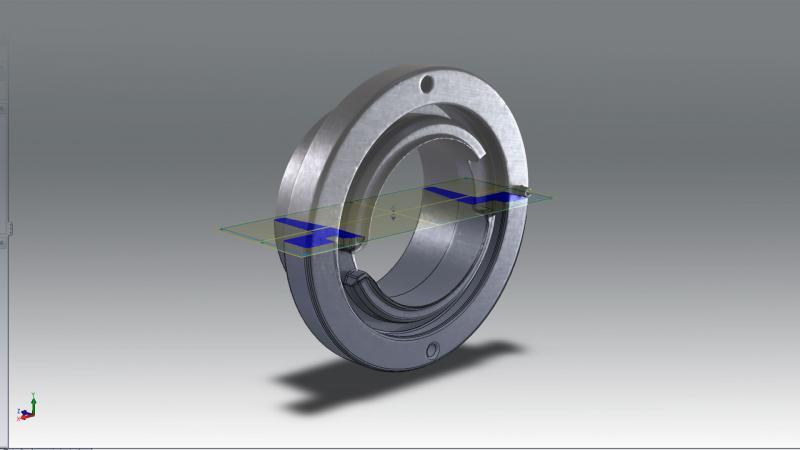
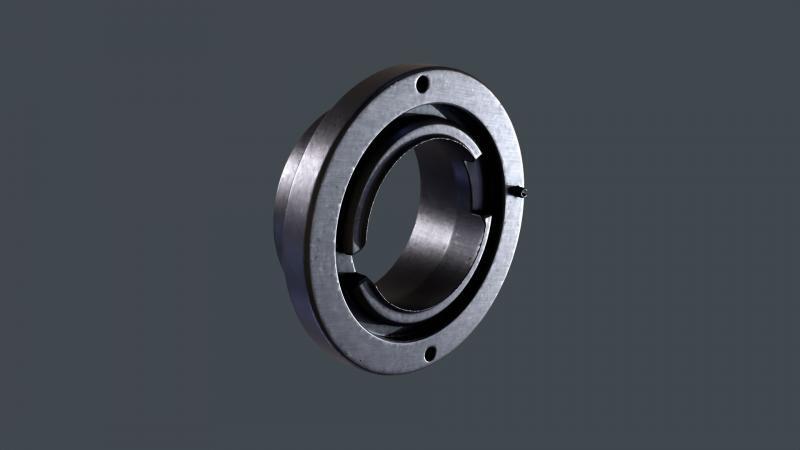
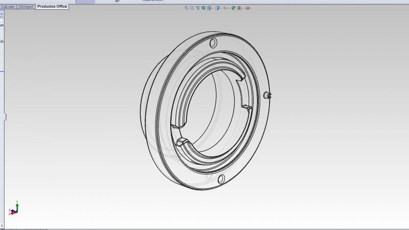
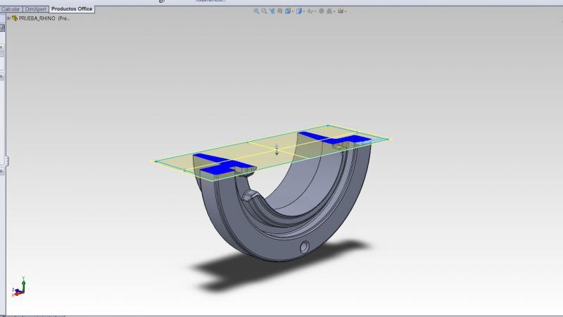
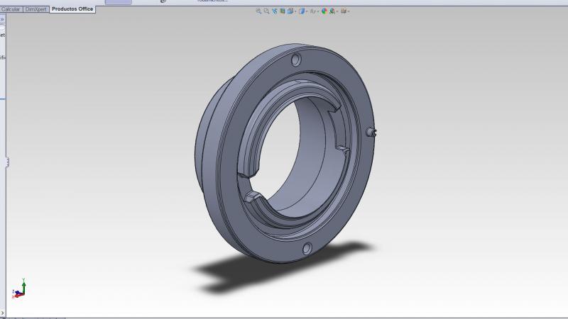
Once the 3D scanning is completed, reverse engineers use specialized software to process and convert this information into a comprehensive and detailed 3D model. This model can be used to understand the original design of the object, make modifications, conduct virtual tests, or manufacture replicas and new parts based on the scanned design.
3D scanning has revolutionized reverse engineering, providing a fast and precise way to obtain information about physical objects without resorting to more invasive and costly traditional methods such as manual measurement or disassembly. However, it is crucial to always respect intellectual property rights and applicable laws when using this technology.
At Scan3D, we use high-definition portable structured light scanners to achieve maximum precision. A structured light scanner is a device that projects a light pattern onto a surface and captures the resulting information to reconstruct a precise 3D image of that surface.
Some of the common file formats used in reverse engineering are:
3D scanning formats. When performing a 3D scan of a physical object, data is generated in different file formats, such as:
Point Cloud: Represents a collection of three-dimensional points describing the outer surface of the scanned object. Common formats include .PLY, .XYZ, .PTS, among others.
3D Mesh: A 3D surface formed by connected triangles. Popular formats are .STL, .OBJ, .PLY, among others.
Parametric surface data: Represents geometry in mathematical forms. They can be proprietary formats of specific software.
Parametric 3D modeling formats:
Once the 3D model has been obtained from scanning or reconstruction, it can be saved in different formats for further manipulation or manufacturing:
.STL (Stereolithography): Widely used format in 3D printing and additive manufacturing.
.STEP (Standard for the Exchange of Product Data): Exchange format for parametric modeling.
.IGES (Initial Graphics Exchange Specification): Neutral exchange format for 3D data.
.CAD (Proprietary format): Software-specific formats for CAD design, such as .SLDPRT (SolidWorks),
.IAM (Autodesk Inventor), .PRT (PTC Creo), etc.
Engineering and analysis data formats:
In addition to 3D models, reverse engineering can involve formats for other types of technical data:
.CSV (Comma-Separated Values): Text format that stores structured data, such as coordinates, measurements, etc.
.XML (eXtensible Markup Language): Text format that allows for hierarchical structuring and storing of data.
It is important to consider that certain formats may be more suitable for specific applications or software. When working on reverse engineering projects, it is essential to ensure that the file formats used are compatible with the tools and software employed in the process.
At Scan3D, we can help you achieve the results you need, with absolute confidentiality.


